This document provides a technical description on the methodology used in the analysis of the vertical profile of the aircraft’s trajectory during the en-route phase of flight. The objective of the methodology is to measure and observe vertical flight efficiency without highlighting specific reasons for the observed behaviour. More detailed case studies are needed to find out reasons for particular observations.
Acronyms and terminology
| Term | Definition |
|---|---|
| FTFM | Trajectory information based on the last filed flight plan |
| GCD | Great Circle Distance |
| PRISME | Pan-European Repository of Information Supporting the Management of EATM |
| RAD | Route Availability Document |
| VFI | Vertical Flight Inefficiency |
Methodology
Approach and assumptions
The general approach of the analysis is to compare the maximum altitudes in the flight plans of flights between a specific airport pair with the maximum altitudes of flights between similar airport pairs, hereafter called reference flights. Reference flights are flights between unconstrained (in terms of RAD restrictions) airport pairs which have a great circle distance close to the one of the examined airport pair.
Since the aircraft type has a significant influence on the nominal cruising altitude, the analysis is done using specific aircraft types with similar performance (e.g. only jet aircraft, turboprop aircraft …) Currently only Airbus and Boeing aircraft are considered since they account for the biggest portion of scheduled commercial flights.
The use of the maximum altitude in the flight plan leads to an underestimation of the vertical flight inefficiency because there can be lower cruise segments before or after the moment the maximum altitude is reached. These cruise segments can be even more inefficient since the fuel consumption at lower altitudes is in general higher.
To account for statistical uncertainty, the lowest and highest 10 percent of the flights (when sorted according to their maximum altitudes) are excluded.
General overview
The analysis is done in 4 major steps. First, the necessary data are extracted from the data source. Then the reference distributions are calculated such that they can be used for all the airport pairs under investigation. For each considered airport pair, the maximum altitudes in the flight plan are processed in order to be compared with the reference. In the last step the different metrics are calculated. The process is visualised in Figure 1.

Figure 1: Different steps of the analysis.
The following paragraphs explain these steps in further detail.
Loading of the trajectories information
The data used for the analysis are downloaded from the PRISME database. FTFM data is used in order to assess the maximum altitudes in the flight plans. The most important data fields for the analysis are the altitude and time information.
Definition of the reference distribution
Reference airport pairs are airport pairs with a great circle distance (GCD) close to the great circle distance of the considered airport pair and which have no constraints in the RAD.
Reference distributions are calculated for buckets of GCD ranges, e.g. a reference is calculated for all airport pairs in the GCD ranges [0,10) NM, [10,20) NM, etc. This approach reduces the calculation time significantly since only one calculation is needed and the reference for a specific airport pair will be the one of the corresponding bucket.
The reference distribution is created using a large number of flights with no specific filtering except for the aircraft type. This is done in order to get a reference distribution irrespective of factors such as aircraft weights, weather phenomena, company policies…
The reference is based on the assumption that flights between airport pairs with similar GCDs, performed with a similar aircraft type, would file for similar maximum altitudes. The differentiating factor between the two sets of flights can be the presence of RAD constraints, scenarios, airline policy, mistakes in the flight planning system, etc., and if the distribution of the maximum altitudes of flights on the chosen airport pair doesn’t follow the reference distribution, this could be an indication of inefficiency.
Distribution of the maximum altitudes
As is done for the reference, the distribution of the maximum altitudes flown on the considered airport pair is determined. Having the distributions of the reference and the considered flow on the airport pair allows for plotting a diagram as in the Figure 2.
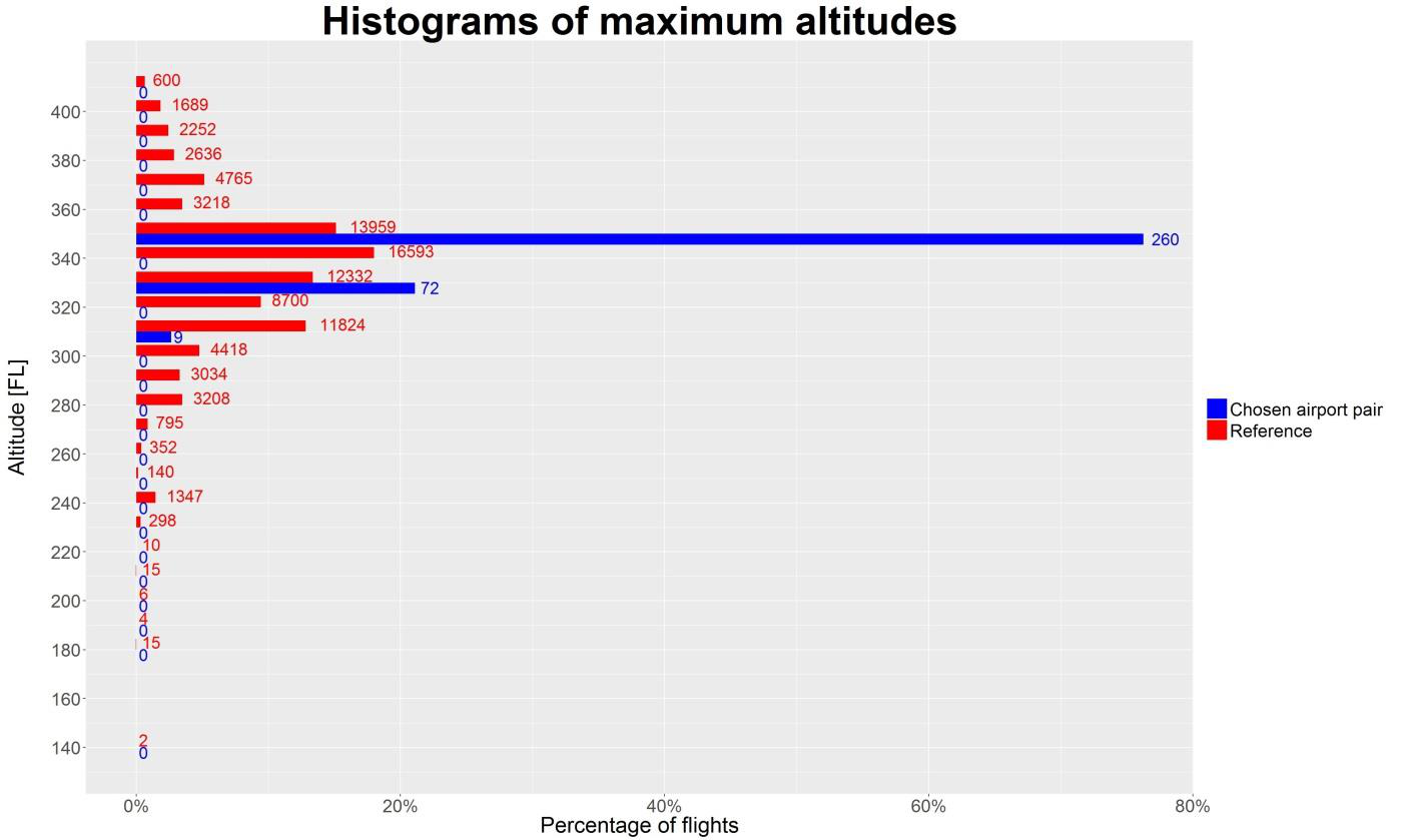
Figure 2 shows the histograms of the maximum filed altitudes both for the reference flights and the flights on the chosen airport pair. The numbers on the right of the bars indicate the number of flights while the length of the bar indicates the percentage of flights. E.g. the large blue bar at FL350 represents 260 flights, being 76.2% of the total number of flights on the chosen airport pair. The sum of the percentages corresponding to the lengths of the bars is 100% both for the blue and for the red bars. As can be seen from the values of the number of flights, there are a lot more flights in the reference distribution which makes it a stable reference.

Figure 2: Example distribution of maximum altitudes.
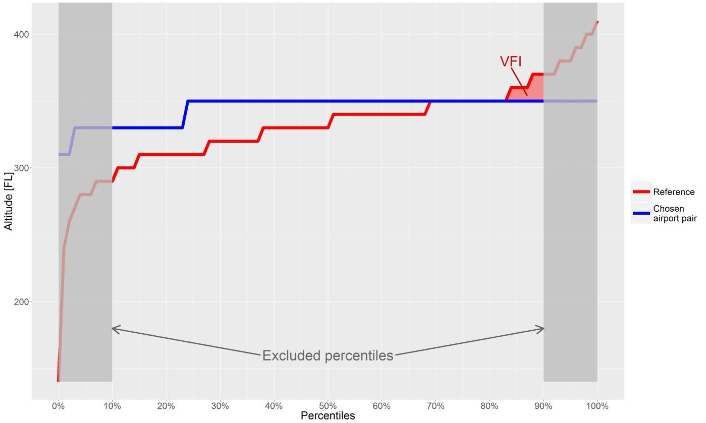
The data in Figure 2 above can be represented differently, using percentiles as shown in Figure 3. To obtain this, the percentages from Figure 2 are simply put successively. E.g. the percentages of the chosen airport pair (blue bars: 2.6% at FL310, 21.1% at FL330 and 76.2% at FL350) are plotted at their respective altitudes to get the blue line in Figure 3. The same is done for the reference.
The example represents an airport pair on which, in general, flights are filing higher than the reference. There are however some percentiles where reference flights are filing higher than the flights on the considered airport pair. Only this part is used in the calculation of vertical flight inefficiency (VFI) in order to flag only the inefficiencies. The red shaded area in Figure 3 indicates the VFI. The dark grey areas on the left and right highlight the percentiles that are excluded to account for statistical uncertainty as mentioned before.

Figure 3: Example distribution of maximum altitudes.
Calculation of the metrics
The VFI is calculated using the percentiles as shown in Figure 3. For each percentile range, the altitude value of the airport pair is subtracted from the reference value. When the airport pair value is higher than the reference value, the result of the subtraction is negative. This might appear as if the flights are more efficient than the reference flights. Nevertheless, the focus is put on finding the inefficiencies so negative values are set to 0.
The result of the percentile range is then multiplied by the number of flights corresponding to the percentile range (e.g. if the width of the percentile range is 1%, the number of flights corresponding to the percentile range is 1% of the total number of flights on the airport pair).
Summing up over all percentile ranges gives the total vertical flight inefficiency. The vertical flight inefficiency per flight value is then calculated by dividing the total vertical flight inefficiency by the number of flights on the considered airport pair (the number of flights for this calculation step is 80% of the total number of flights on the airport pair since the lowest 10% and highest 10% of the flights are not used).
Table 2 summarises the formulas used for the calculation of the VFI metrics.
| Result | Formula |
|---|---|
| Total vertical flight inefficiency (Total VFI) | \[VFI_{\mathrm{tot}} = \sum_{i} \max(L_{\mathrm{ref}, i} - L_{\mathrm{act}, i}, 0) \cdot n_{\mathrm{act}, i}\] |
| Vertical flight inefficiency per flight (VFI per flight) | \[\frac{VFI_{\mathrm{tot}} }{\sum_{i} n_{\textrm{act}, i}}\] |
With:
| Symbol | Description |
|---|---|
| \(i\) | Percentile range |
| \(L_{ {ref}, i}\) | Flight level of the \(i^{th}\) percentile range over all reference flights in the GCD bucket around the GCD of the considered airport pair. |
| \(L_{ {act}, i}\) | Flight level of the \(i^{th}\) percentile range over all flights on the considered airport pair. |
| \(n_{ {act}, i}\) | Number of flights on the considered airport pair in the percentile range. |
Further Information
For further information please refer also to (S. Peeters et al. 2016; Sam Peeters and Guastalla 2017).